
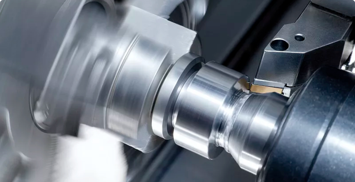
A Practical Guide to Precision Curved Surfaces and Flat-End Tool Machining
In precision mechanical manufacturing, CNC turning plays a critical role in producing complex components—especially parts with curved surfaces and tight radius tolerances. For CNC machining companies serving international markets, clearly demonstrating expertise in radius control, tool selection, and advanced machining strategies is essential for building technical credibility with global customers.
This article provides a practical and engineering-focused overview of how radius tolerances are controlled in CNC turning through proper tool selection, process planning, and parameter optimization. It also addresses a common technical question from customers: How can a flat-end tool machine a curved bottom surface?

- Core Challenges in Radius Tolerance Control During CNC Turning
- Practical Strategies for Accurate Radius Control
- Tool Selection and Parameter Optimization for Curved Surfaces
- Standardized Machining Process for Precision Radius Features
- How Can a Flat-End Tool Machine a Curved Bottom?
- Conclusion
1. Core Challenges in Radius Tolerance Control During CNC Turning
When machining curved profiles such as spherical surfaces or blended radii, CNC turning faces two primary accuracy challenges:
1.1 Tool Nose Radius–Induced Profile Deviation
To improve tool life and surface finish, turning inserts are manufactured with a nose radius (typically R0.4–R1.6 mm). However, CNC systems program the path of a theoretical tool tip, while the actual cutting point lies along the curved insert edge.
As a result, when machining arcs or tapers, the actual profile may deviate from the programmed geometry, leading to undercutting or overcutting.
For example, when machining a 10 mm radius spherical surface using an insert with a 0.4 mm nose radius, the theoretical profile deviation can exceed common precision tolerance requirements if compensation is not applied.
1.2 Ball Screw Backlash and Directional Error
Even high-precision ball screw systems have minimal backlash. During turning operations that require reverse feed movement—such as internal radii or stepped profiles—this backlash can cause positioning inconsistency and dimensional variation.
2. Practical Strategies for Accurate Radius Control
2.1 Tool Nose Radius Compensation (G41 / G42)
The most effective way to control profile accuracy is by applying tool nose radius compensation.
Instead of programming the tool path based on the insert geometry, the programmer defines the final part contour, and the CNC control automatically offsets the tool path based on the measured insert radius.
This method is a standard practice in modern CNC turning and is essential for maintaining consistent contour accuracy in curved profiles.
2.2 Eliminating Backlash Through Programming Strategy
To reduce the influence of backlash, programmers often use a “single-direction approach” strategy.
For example, when approaching a final diameter after reverse motion, the tool intentionally overshoots the target position and then returns to the final dimension from the same direction. This ensures consistent contact within the ball screw system and improves dimensional repeatability.
3. Tool Selection and Parameter Optimization for Curved Surfaces
3.1 Tool Selection for Different Radius Features
General curved surfaces
For most external radii, fillets, and blended contours, standard turning inserts with appropriate nose radii (R0.4 or R0.8) are suitable. The radius should be selected based on surface finish requirements and clearance conditions.
Complex surfaces and flat-bottom features
For components with complex internal geometry or curved bottoms—commonly found in molds or structural parts—flat-end milling tools are frequently used on CNC turn-mill centers.

Although flat-end tools do not have a curved cutting profile, their controlled multi-axis movement allows them to machine curved surfaces through precise interpolation.
In high-precision applications, specialized flat-bottom tools with ultra-straight cutting edges (flatness within approximately 0.02 mm) may be used. These tools can machine flat or curved-bottom features through controlled eccentric rotation and circular cutting paths.
3.2 Key Machining Parameters
Cutting speed and feed rate
For finishing curved surfaces, higher spindle speeds combined with lower feed rates are commonly used to improve surface quality. Final parameters depend on material properties (aluminum, stainless steel, titanium, etc.) and insert geometry.
Step-over and tool path spacing
When machining complex surfaces using ball-end or corner-radius end mills, step-over distance directly affects surface scallop height. Smaller step-overs improve surface smoothness but increase machining time.
For relatively gentle curves, corner-radius end mills often allow larger step-over values compared to ball-end tools, improving efficiency in roughing and semi-finishing stages.
Entry and exit strategy
Smooth entry and exit paths are critical. Whenever possible, tool paths should extend beyond the functional surface to ensure stable cutting conditions and avoid visible tool marks at transition points.
4. Standardized Machining Process for Precision Radius Features
To achieve stable and repeatable results, curved components are typically machined in multiple controlled stages:
4.1 Rough Machining
Objective: Rapid material removal
Bulk material is removed using rigid tools and layered cutting strategies. For curved geometries, contour or Z-level roughing is commonly applied. Adequate cooling is essential to maintain tool life.
4.2 Semi-Finishing
Objective: Shape refinement and uniform stock allowance
This stage removes roughing marks and prepares the surface for finishing. Ball-end or corner-radius tools are typically used, leaving a consistent allowance (commonly ~0.5 mm).
4.3 Finishing
Objective: Final dimension, geometry, and surface quality
Tool nose radius compensation is fully applied. Cutting parameters are optimized for stability and precision, with shallow depths of cut and fine feed rates. For complex surfaces, continuous contour tool paths are preferred.
4.4 Surface Refinement (When Required)
For parts requiring very low surface roughness (e.g., Ra ≤ 0.8 µm or lower), additional processes such as polishing or fine grinding may be applied after CNC machining.
5. How Can a Flat-End Tool Machine a Curved Bottom?
This is a common question from customers unfamiliar with multi-axis CNC machining.
A flat-end tool refers to the geometry of the cutting edge, not the final shape it produces. While the tool itself is flat, CNC machines can control the tool’s movement in multiple axes simultaneously.
Machining Principle
By programming precise interpolated motion, the tool’s center follows a calculated three-dimensional path based on the target radius or spline geometry. As the tool moves, its cutting edge gradually removes material, effectively generating the curved surface through a milling process.
Accuracy Considerations
Final accuracy depends on:
- Machine positioning and repeatability
- Interpolation algorithms
- Tool path planning density
Advanced interpolation methods, such as tangent-approximation strategies, can reduce profile deviation compared to simple linear segmentation, especially for high-precision curved features.
Conclusion
Accurate radius tolerance control in CNC turning is the result of a systematic approach—understanding error sources, applying correct tool compensation, selecting appropriate tooling, and following structured machining stages.
For CNC machining companies serving international customers, clearly communicating these technical capabilities helps build confidence and demonstrates process control expertise. By applying standardized methods and disciplined machining practices, manufacturers can consistently deliver precision curved components suitable for demanding industries worldwide.

Leave a Reply